

Entry posted by mambosasa
2,817 views
I have been looking forward to a simpler task all project long and as far as I am concerned, this is it.
So, before we get into it, the question is - were there any Santa's little helpers today? YES!
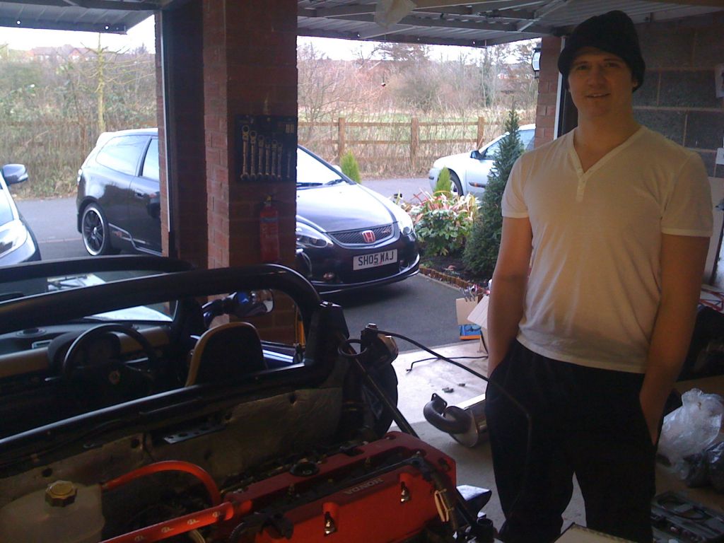
I was glad to see a good friend of mine that I have know from when he as a little kid ( and now towers over me like a giant! ![]() ) who happens to have a pretty nice black CTR.
) who happens to have a pretty nice black CTR.
This is he...
Down to work.
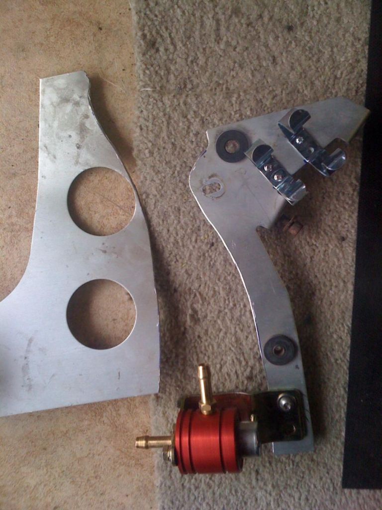
The kit comes with fuel hoses, a fuel filter, a pressure regulator and the associated clips.
The approach should be pretty much the same as the coolant hoses. Measure, cut, install, clip! That simple.
The first job though was to find a mounting place for the bits. People tend to have their own interpretation of what they believe the layout should be, but however you choose to route the pipes, the most important sequence is as follows:-
Fuel should flow:-
Tank - Filter - 'T' off to the engine fuel supply - 'T' off to the pressure regulator - then back to the tank
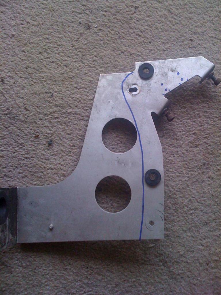
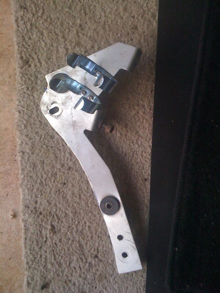
Mounts
I chose to modify the aluminium plate that used to hold the original air filter and cut it down to a manageable size to allow the mounting of the fuel filter and the pressure regulator.
A bit of dremel work, marking for the holes etc and paint, it was all sorted.
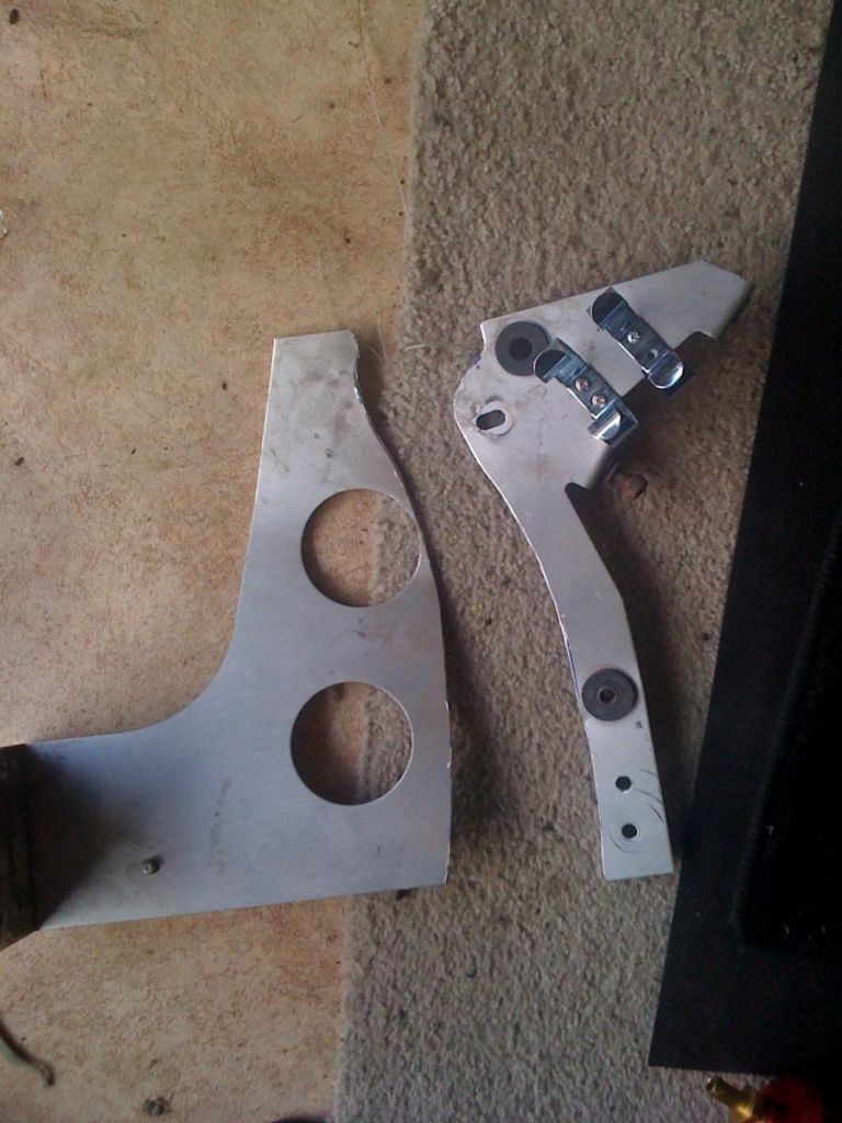
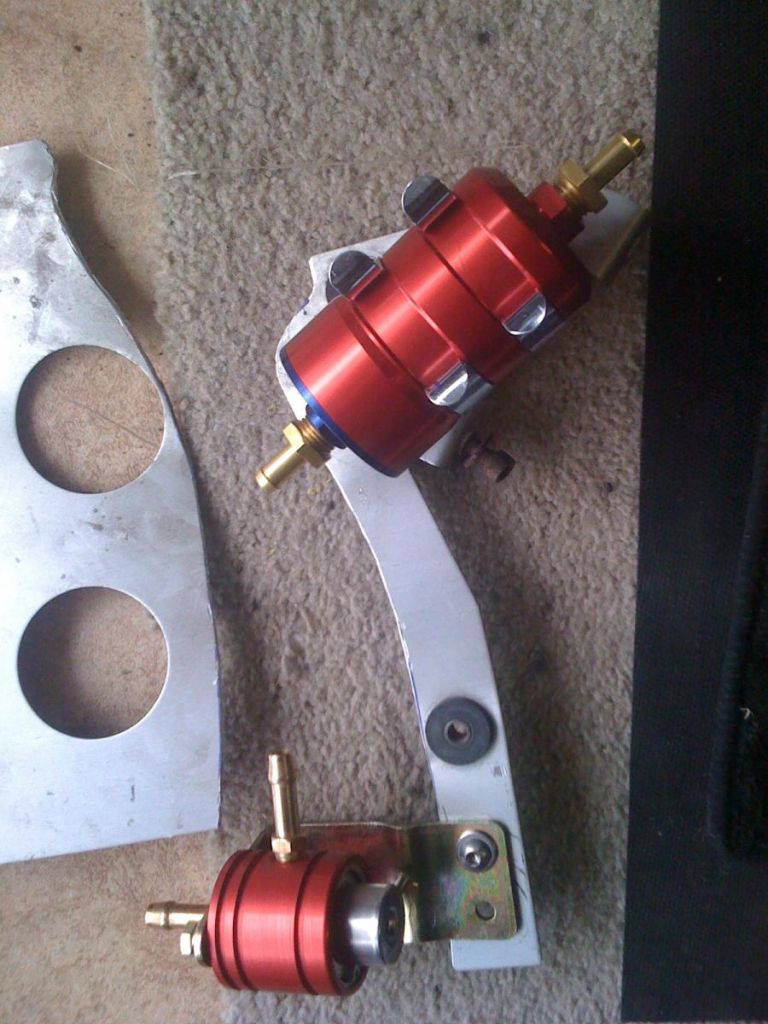
Then it was a matter of bolting the plate back on the bar.
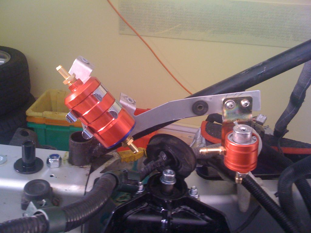
Once I was happy with the location and general layout, it was then down to measuring and cutting...
NOTE: All original connections are re-used for the installation. So, that is two connectors onto the fuel tank, and one connector to the engine (Original Honda part). These must be cut off to release them from the original pipework.
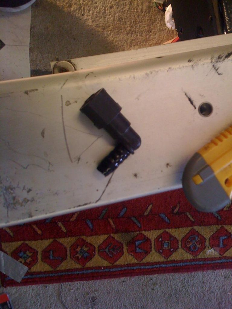
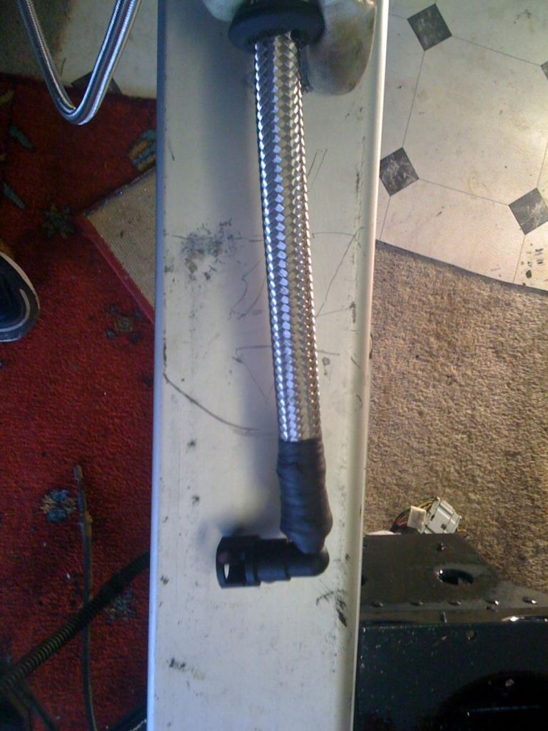
Connected to the pipework...
NOTE: I used waterproof shrink tape to cover the joint for extra security.
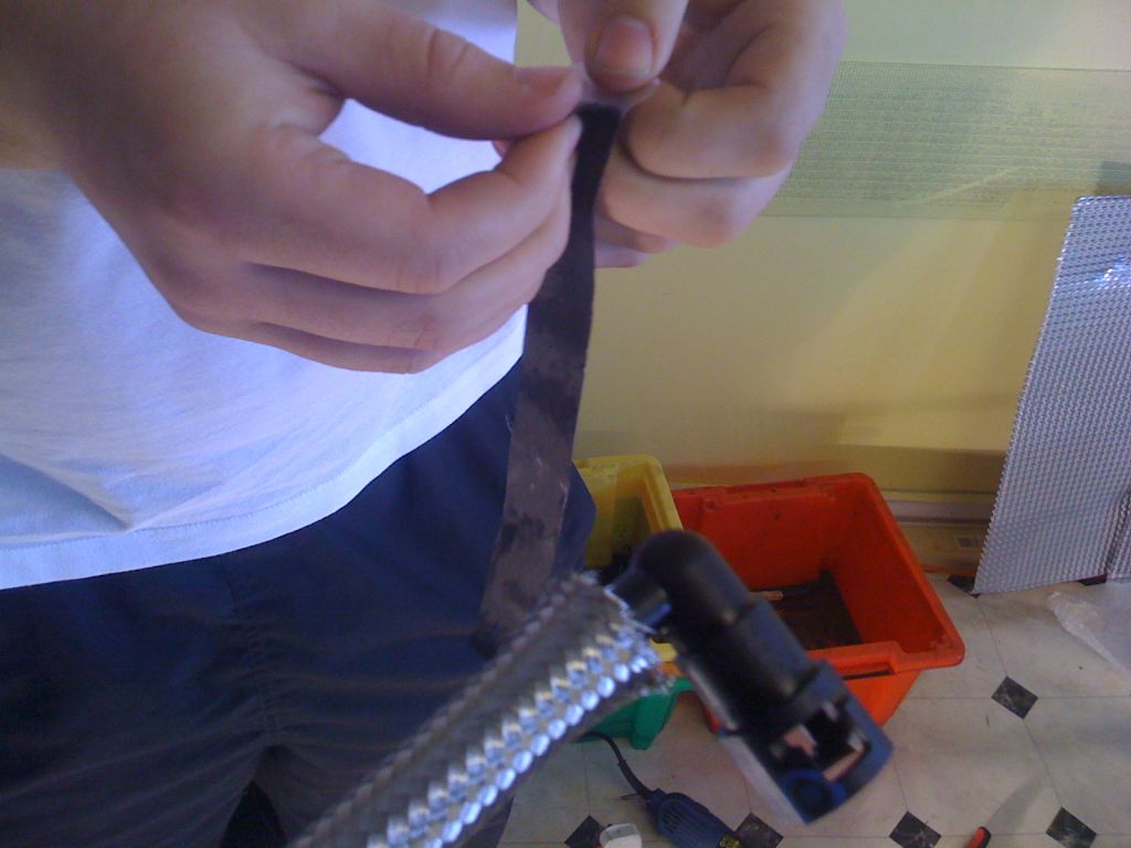
The clips were added later.
Notice that for the pipes going back to the tank, you will have to feed through the original rubber grommets. These will have to be expanded to fit the new thicker pipes.
An hour and half later...
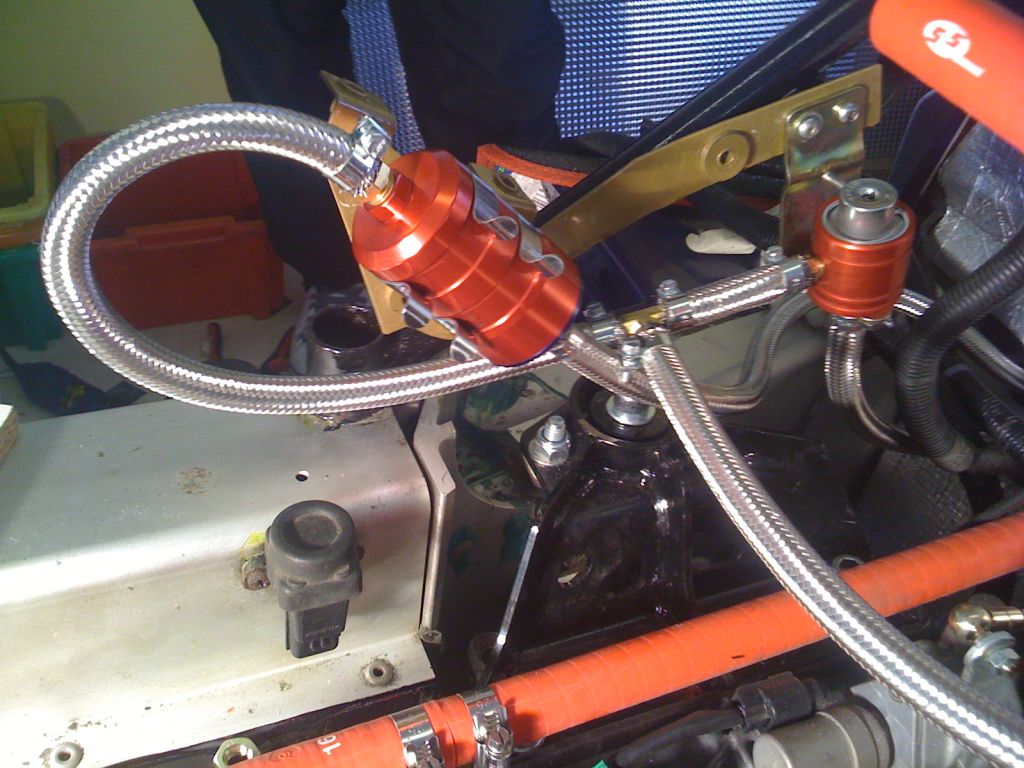
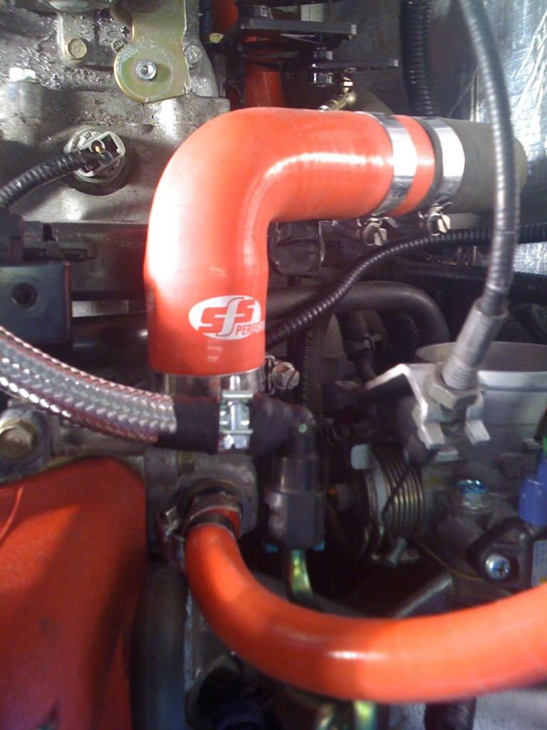
Connection to the engine...
At this point, I would like to point out that I am not completely happy with the layout as yet. It is functional and it will work fine, however I think it could be neater. I will have a think and may change it at a later date (well, before completing the project anyway)
Otherwise, job done! ![]()
2 Comments
Recommended Comments