

Required:
- A suitable switch
- A length of wire
- A few connectors
- Soldering iron and a bit of solder
- Black tape
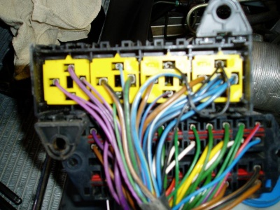
I've been tinkering again - I've thought for sometime it would be good to have a manual fan switch. Mostly for use on track days but I'm sure it will come in useful if we ever have a summer and I'm stuck in traffic. I've had a nosey and this is how it works (I think). The fan is switched on via a relay due to the load currents. This is controlled by the MEMS ECU. The positive side of the relay coil is always live when the ignition is switched on. The ECU grounds the other side of the coil when the fan is required. After a question on SELOC as I could not find a car wiring colour code for the Lotus, it turns out the wire is Blue and slate Grey. A pic of the underneath of the relay box with the wire:
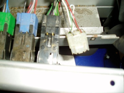
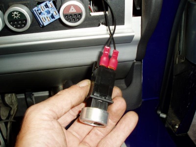
 The wire I wanted is the second one from the left on the top. I've bought a switch and took the dashboard apart as well. It turns out the dummy switch (the one to the right of the headlight switches etc.) has some connections on the back. I've no idea what these are for:
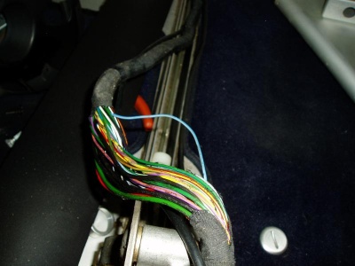
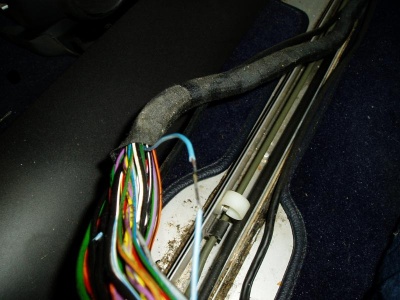
 I traced the Blue / Grey wire to see where it went to see if I could make the job easier. It turns out it runs in the centre console of the car. Obviously on the way to the ECU. I stripped off the tape on the loom with a craft knife:
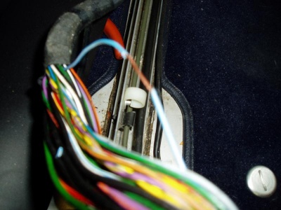
 I'm not wildly keen on cutting wires in cars. I've therefore stripped the wire ready to solder another wire to it:
 Next I tinned the stripped wire with solder:
 Attached the wire to go to the switch:
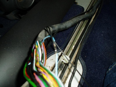 Also taped the section of the loom I had stripped, you can see the new wire coming out for the switch:
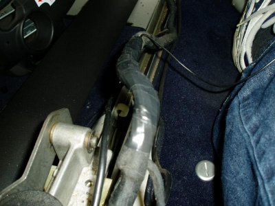 I cable tied this along the existing wires till we got under the dash. The fun part was being upside down in the footwell trying to thread the new wire to the existing switches. Once I had done this, I used the existing black wire off the dummy connector (ground) to one side of the switch and the new wire to the other side. A couple of connectors later:
 A small sticker on label and we are done:
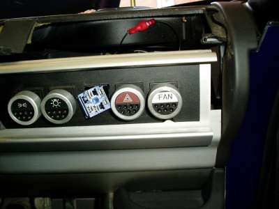 Surprisingly it works. The switch missing in the final picture is my fog light switch. This is deceased I found whilst doing the job. I'm going to order a new one. I may try and get the lights in the switch working at a later date but I've got to get the rest finished before Donnington on Tuesday. It will have to keep for now.


.thumb.JPG.8b430cdf432e55b4f884027eff0f6f45.JPG)

Recommended Comments
There are no comments to display.
Join the conversation
You can post now and register later. If you have an account, sign in now to post with your account.