

Martin R
-
Posts
8,316 -
Joined
-
Last visited
-
Days Won
36
Recent Profile Visitors
27,617 profile views


Martin R's Achievements
")


-
 looks better than ever Bis.
 -
Stunning job refurbishing my alloys at a reasonable price. A pic tells a thousand words.
-
Normal Clarkson trying to be controversial. Drumming up interest for the new series of Top gear? However a fair bit he says about Chapman is correct. He was a genius. he also turned this into tax avoidance. He should maybe have worked for Google? Clarkson should stick to just reviewing cars. However this is the last thing Top Gear is actually about.
-
A Huge Thanks To Essex Autosport
Martin R replied to LIVY's topic in Unsponsored company promotion/Discounts/Benefits
I didnt say i would do it Bill. A 1.9K is the way forward if you like getting your hands dirty -
A Huge Thanks To Essex Autosport
Martin R replied to LIVY's topic in Unsponsored company promotion/Discounts/Benefits
Rich, consider a Duratec as well before making a decision. I expect Steve Williams 250 bhp conversion goes quite well -

© © MLOC 2010
-
© © MLOC 2010
-
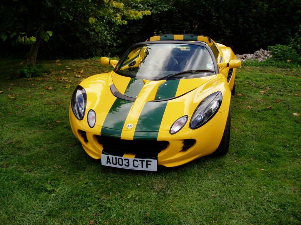
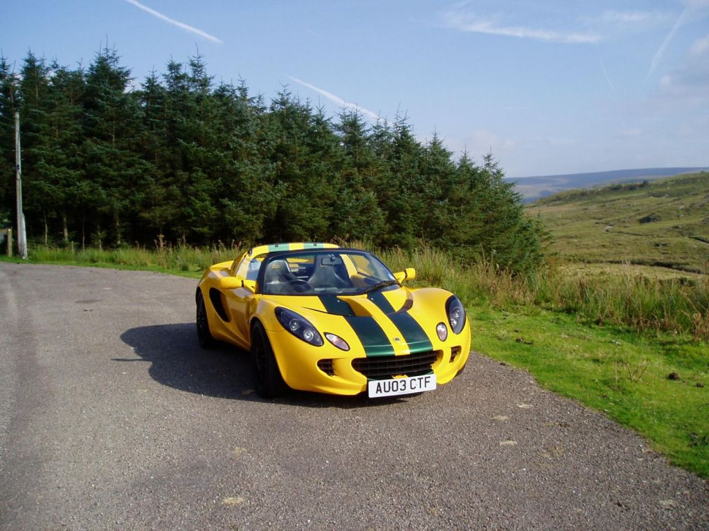
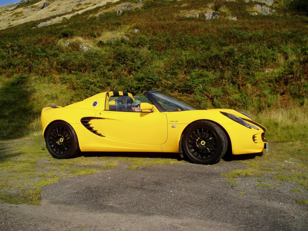
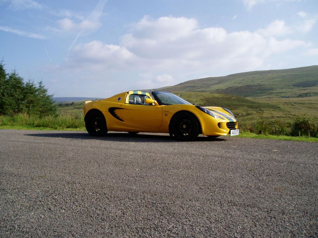
Lotus Pics
-
-
-
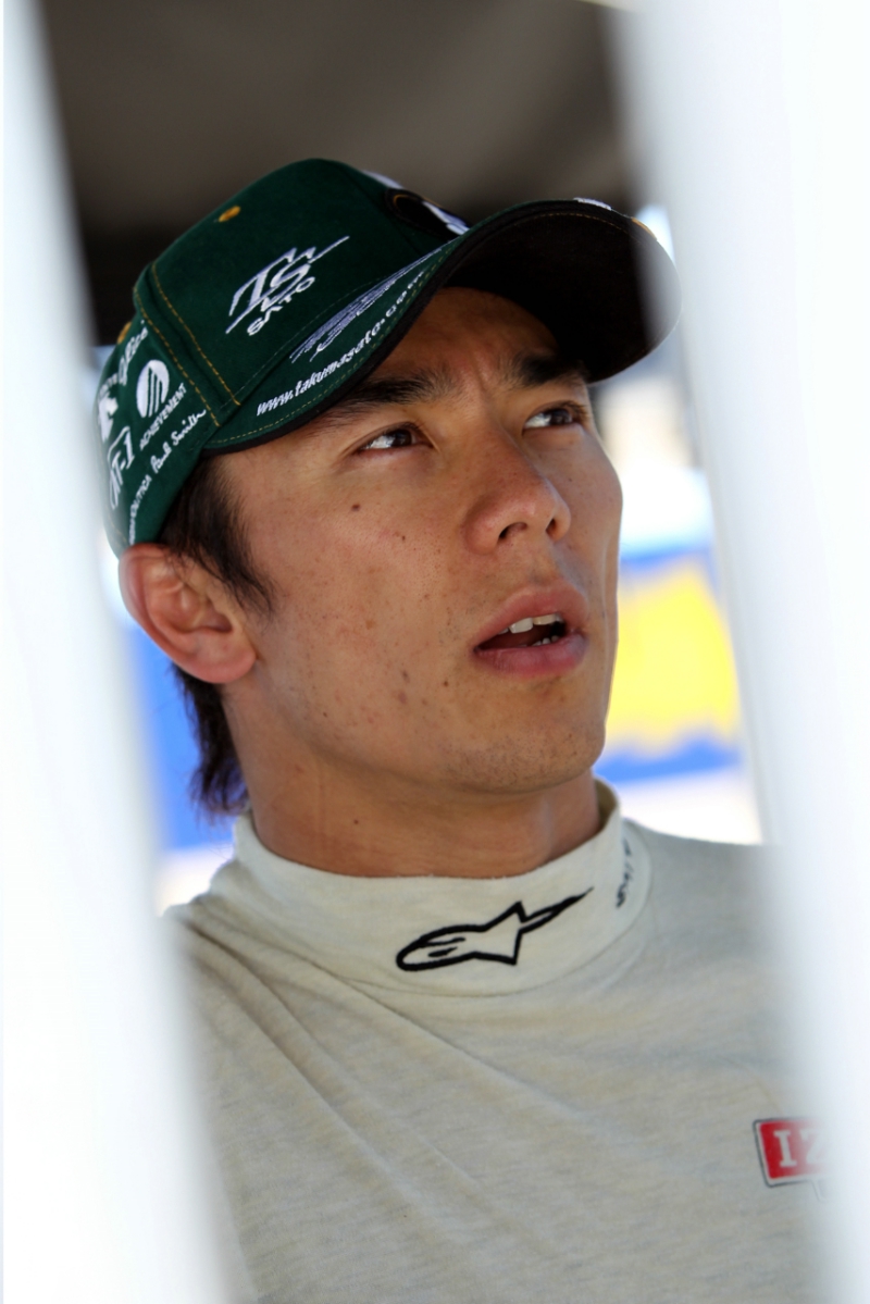
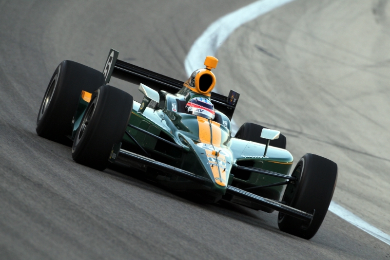 Takuma Sato will start the latest round of the IndyCar Series from inside the top ten after a solid showing in qualifying at Chicagoland. On his return to oval action, Taku was in impressive form at the wheel of the #5 Lotus – KV Racing Technology end as he lapped the 1.5 mile oval at an average speed of 214.945mph. That means the former F1 racer will line up tenth on the grid for the Peak Antifreeze & Motor Oil Indy 300, sharing the fifth row of the grid with Ryan Hunter-Reay. "I am very happy with how today went," he said. "We worked on race trim for most of the morning session and the qualifying set-up. "During qualifying I watched how other drivers took the racing line so I could get a better understanding. I am really pleased to be starting tenth and look forward to the race."
 -
Three Kvrt Drivers Deal With Tough Track Conditions In Practice
Martin R posted a news article in Lotus Indycar
 Mario Moraes, who finished fourth last year at Infineon Raceway, led the KV Racing Technology three-car lineup Friday in the opening practice round for Sunday's Indy Grand Prix of Sonoma. Moraes, driving the No. 32 KV Racing Technology Honda/Dallara/Firestone car, posted an average speed of 104.831 miles per hour on the demanding 2.30-mile, 12-turn circuit north of San Francisco. Dario Franchitti was the fastest Friday at 105.889 m.p.h. Moraes, who has three top-ten road course showings in 2010, scored his best road racing finish here a year ago in the KVRT machine when he came from 14th to fourth in the 75-lap contest. Moraes is seeking a better qualifying spot this year in an effort to challenge for a podium placing on Sunday. Hot track conditions made for a slippery surface Friday. E.J. Viso, who led nine laps at the Sonoma event in 2008, drove his No. 8 PDVSA — KVRT Honda/Dallara/Firestone entry to a speed of 104.382 m.p.h. Viso is seeking to return to the Firestone Fast Six qualifying round on Saturday. He made the Fast Six at Edmonton. Formula One veteran Takuma Sato, a rookie in the 2010 IZOD IndyCar Series, made his Infineon Raceway debut today in the No. 5 Lotus-KV Racing Technology Honda/Dallara/Firestone car. The Japanese star recorded an average speed of 104.090 m.p.h. Sato, who qualified third at Mid-Ohio two weeks ago, has qualified for the Firestone Fast Six rounds in all three of the previous permanent road circuit events at Barber, Watkins Glen and Mid-Ohio. Qualifying is set for 2:30 p.m. (PDT) Saturday with Sunday's race scheduled at 2:45 p.m. (PDT). The Indy Grand Prix of Sonoma will be televised live on the VERSUS Network. DRIVER QUOTES: MARIO MORAES – No. 32 KV RACING TECHNOLOGY HONDA/DALLARA/FIRESTONE: "Overall, it was a good day. I really like this track. It is one of the most challenging on the circuit. We are looking over the data and we had a couple of things that posed a problem. We had a brake problem. The brakes are being changed for Saturday. Unfortunately, we are in the hard qualifying group but we really want to make the top six out of there. We need to work harder to get into the second qualifying round. Last year, we finished fourth here. We need to really work on the fuel strategy for Sunday to make it a two-stop race." EJ VISO – No. 8 PDVSA – KV RACING TECHNOLOGY HONDA/DALLARA/FIRESTONE: "The track surface was different today from where it was last week (in testing). The things that worked for us last week didn't really work today. We need to analyze the data that we had from last week with the data from today. If we can get the information sorted out, I think we can be good for qualifying. This is a track where you can overtake. But you really want to qualify up front and race with the fast guys earlier in the race. That is our goal for Saturday." TAKUMA SATO: No. 5 LOTUS – KV RACING TECHNOLOGY HONDA/DALLARA/FIRESTONE: "It was a reasonable day. The track condition was slippery at the beginning of the practice session. But we also had a little struggle on the balance of the car. At the end, the track and weather conditions got better but we need to get more grip. We wanted to try some more things with the car. But we ran out of time today. We will analyze the data from today. Hopefully, we can put everything together and be ready for a strong run tomorrow (Saturday)."
 -
This is how i did it. I changed mine from the usual anti freeze to the OAT stuff. Take the 2 appropriate hoses off using the service manual guide. They are either side of the sills at the rear. Flush through using a hose as well as possible. Refit hoses. Refill system using plain water and Halfords radiator flush. Pressurise system using the Halfords esze bleed and the appropriate cap to fit the expansion bottle and a spare tyre. Make sure the spare tyre is not over inflated as you dont want to blow the hoses off. Open the bleed screw on the engine cooling rail till you only get fluid out. Open the bleed screw on the hose coming from the radiator. Its a knurled brass thumb screw IIRC on the passenger side. You can just about access this from the front services compartment on a S1. Open it till you just get fluid out. Remove esze bleed. Leaving the cap off the expansion bottle, start the car and let it idle till the temp reaches 65 ish. Hold the revs at 2000 rpm till you see the thermostat open at approx 85, it should then drop to about 80. Let this happen twice. You should then rebleed just the front radiator bleed using a rag to make sure you do not burn your fingers. Turn the car off and let it cool. You should then repeat this procedure but fill up with OAT anti freeze instead. You may have to repeat the bleed procedure a couple of times if you have variable temperature readings. I was quite suprised how much anti freeze was left in the system when i drained the radiator flush. If you are changing to OAT, you need to do a thorough flush as the OAT does not mix with OE antifreeze. The 2 if mixed will form a sludge apparently. Dont forget to pump the spare tyre up.
-
There is nothing particularly complex about bleeding the K series clutch. The line can be bled using the traditional 2 person technique (one pumping pedal, the other operating the nipple on the slave cylinder), but a pressure bleeding system such as a Gunsons Eezi-bleed makes it an easy 1 man job. A useful tip is to pull back the lever on the slave cylinder (gearbox) end whilst bleeding as there is potential for air to get trapped in the very end of the cylinder.
-
As its the winter and the little blue bomber is going sprinting next year ive decided on a suspension refresh. Ive bought some Superflex bushes and a set of ball joints. With the fixings etc it should work out at about £400 for the lot. If anyone needs any fixings BTW PM me before you buy and if i have them you can have them at what it cost me. Im also shotblasting the wishbones and replating at the same time as im a fussy so and so at the best of times. Pics to follow when ive cleaned a bit of blood of my knuckles. The story so far. Ive taken the front clam off. Ive shotblasted and repainted the front towing eye with Hammerite smooth. The spray can version as though its thinner and needs more coats the finish is spot on. Ive replaced the driving light brackets after a couple of additional coats of Hammerite again. These are a reasonable £8-50 per side Ive removed the front passenger side hub and top wishbone joint. A few pics. Front off Side view Superflex bushes ( 22mm stainless internal sleeve ) The bottom ball joint carrier and steering arm. Ive shotblasted both and yes you have guessed give it the Hammerite treatment. Although where the ball joint and steering arm attaches ive left it just shotblasted. Ive done this by putting a bolt and appropriate sized washer through the hole before spraying. Side view Bottom view You obviously dont want to Hammerite the parts that attach it to the hub carrier as you have to coat these with Duralac ( spelling ? ) to prevent electrolitic ( spelling ? reaction. This is turning into a ramble but a couple of other things i forgot i had done. Ive replaced the fixings for the radiator and radiator surround with stainless steel for when the plastic end caps pop as they seem to do on S1,s. They were really rusty and a PITA to remove. I also had a spot of bother with the sill fixings on the front clam and had to saw 3 out of the 4 off ( deep joy ) Ive sourced a supply of 8mm flanged Aluminium rivnuts to replace them with at a very reasonable £3 for ten. From here http://www.nfauto.co...consumables.htm Edit, i also tightened up the jubilee clips on the radiator hoses and 1 was quite loose Anyway back to pics Cleaned up front hub carrier Top view showing steering arm about to be retightened ( if i had the new fixings ) note the shims used to adjust the front wheel camber. Incase anyone needs them, these are some usefull part numbers. Ball joints QSJ883S (QH) Track rod end QR2382S (QH) These are the same parts that TADTS.com supply. Most motor factor places should be able to supply them so there might be a few pennies saved by shopping around. Next episode The first pic shows the refurbed top wishbone and new ball joint, also i did the top damper bracket as well. You might just be able to see the grease i put on the ball joint rubber to allow it to be pushed through the wishbone. Next pic shows the front of the ball joint housing on the wishbone. It has 2 small holes in. Ive though about this and i can only presume its to let the water out to stop it sitting on top of the ball joint. Only a guess mind. I put a little gob of greae in before spraying to stop it being blocked up with paint and removed it after. Next one is the poly bush eye. Nice and clean I was very carefull not to get any paint on the front edge as the top hat of the new bushes sit on here. This pic is going to take a bit of explaining. On the front top wishbone you have washers to adjust the castor of the front wheels. 4 on the front leg and 4 on the back. These can be arrange either 1-3, 2-2 or 3-1 either side of the bush eye. The front and back legs are always the same arrangment. Mine were 2-2. You have to be careful as you take the wishbone off to spot it. One of the old shim washers also has rubber on it ( snubber washer ) This is to prevent metal to metal contact on the OE bushes as you only have a top hat one end. The new bushes have a top hat either end as they come in 2 parts, so you do not need a snubber washer. Ive tried to lay this pic out as old and new set up, see what you think. Ive just noticed i missed the right hand poly bush out the pic It should be next to the right hand Stainless steel insert. Hope you still get the idea. Next pic is the wishbone with the bushes and inserts in place. Last one is the reassembled wishbone on the car. Ive read as much as possible on this subject before attempting the job. This is the theory reagarding POLY wishbone bushes as i see it. Hopefully someone will put me right if im wrong. The steel insert is gripped on the chassis and does not turn in use. The poly bush should not turn in the wishbone eye in use. The bolt does not turn in use. The only parts that turn in use is the wishbone eye and the poly bush which turn together not independant of one another. I mention this as i thought long and hard about which bits to grease on reassembly. I put no grease between the eye and outside of the bush. I greased the inside of the bush the outside of the top hats on the bush and a bit on the washers. No grease on the bolt. Im hoping this is correct. On the SELOC tech wiki it says you can torque the wishbone bolts on poly bushes without the car being at ride height. Im sure this is correct. However on the packet with these poly bushes it says torque at ride height, so im going to do that. Although i did torque them to 45 NM to check the operation to be on the safe side. Im pleased to say the bushes are not turning in the eye and the bolt is not moving either. The up and down movement seems to be nice and smooth so i presume all is well. Last thing i did was to loosen the bolts ready for final reassembly later. Im now going to have a drop of wine Hopefully we will catch some of you at Donny tomorrow. Right next pic is the lower wishbones now off. Ive made sure the tea cup is in the pic just for Ladders. On this pic ive tried to show the top hat end and the none top hat end on the OE bushes. For those that have not read the SELOC tech wiki, this is how you remove the OE bushes. I used a 18mm and a 30mm sockets in a engineers vice. You have to break the rubber top hat using the 18mm socket and push it through into the 30mm socket. I put in a bit of old rag to protect the sockets from damage. You have to be carefull the sockets are aligned correctly. If the vice goes tight whilst you are doing it, they are not right. Ready to go On the way Jobs a good un The hardness of the OE bushes did suprise me when i took them out. They are rock solid to a laymen like me. Mark A might explain how they work. As far as i can see they must rotate around the bolt as you could not get enough travel otherwise i would have thought. The poly bushes do seem to move nicely but im only pulling them up and down in the garage. We shall have to see. I would regard a good 1/2 and 3/8 inch socket set a necessity. Also a small set of deep sockets and off set spanners as well as normal ones. Ive also got a ball joint splitter the one you clamp on. I could not bring myself to use the one you hammer on my pride and joy A decent torque wrench as well. Also a hex socket set, which you can get for about £10 These save a lot of messing about with Allen keys. You also obviously need a jack etc. If i think of anything else i will add it to this list. Ive used black hammerite smooth to spray the wishbones as i like the finish. You could buy a tin and brush it on but i doubt the finish would satisfy a GJOB like me. There has been a bit of discussion on SELOC regarding painting wishbones. Some people seem to think it could hide spreading rust under the paint. As ive shotblasted mine first ( pics to follow when i do the lower wishbone ) I dont regard this as a problem. HTH. Edit. You will also need a nylon headed hammer or similar to remove the brake discs are they are a touch stubborn. A couple of pics of the shotblasted lower wishbone whilst i wait the paint drying. Im also waiting for some Permabond A131 to be delivered for the rebuild. One side. Other side. Not the worlds best pics but i think its fair to say they are clean and rust free. Right here we go again. Sorry about the delay. Ive had the bottom wishbone on and off a couple of times as the bushes squeeked. Ive sorted it now. A bit of the weld on one of the eyes to the wishbone was stopping the bush seating properly. It needeed a small amount of carefull fettling. First pic, lower wishbone after painting. Lower wishbone with bushes in. I also attached the lower plinth and torqued up the ball joint as it was easier with it off the car. Lower wishbone back on the car again. Dont forget to coat the surfaces of the parts that attach to the hub carrier with Duralac. Also coat the threads of the bolts with Permabond A131 as this stops the corrosion as well. The hub carrier is back on the car. Ive also coated the hub face with copper slip. This is so you dont have to spend 15 mins hammering the brake disc with a nylon hammer next time to get it off. Wheel on and back at ride height and being torqued up. Now finished and just to round it off a new stainless steel brake hoses retaining clip. A picture of the tools ive used so far. Its easier if you remove the bottom anti roll bar mount fixing when you are putting the bottom wishbone back in. 1 down 3 to go. QUOTE(Steve J @ Nov 25 2006 @ 07:13 PM) *) Are you sure coating the hub with copperslip is a good idea? Just wondering whether the rotation will splatter the copperslip over your brake disks and cause stopping problems? Steve, there is a sizable lip between the hub face and the back edge of the disc. I will post a pic up when i get the other one off. I removed the rust off the inside face that mates to the hub using a wire mop in a drill. I will have a good nosey to make sure none is getting through though. A couple of other things ive thought of though. If you are taking both wishbones off put the bottom one back on first as the top one falling down in front of your face gets on your t*ts. Also make sure the steel bonded inserts in the chassis are really clean. These appear to be hardened steel and the wishbone retaining bolts go through them. If they are not really clean the wishbones are tight going back in QUOTE(Mark A)Just a quick comment. The original OE bushes do not rotate around the bolt. The inner sleeve is clamped solidly and doesn't rotate. The rotation of the wishbones is done via wind-up of the bush, remember that the forces exerted by the suspension are massive compared to what you can do by hand. This is why it is very important that you fit the bushes in the correct orientation, and why the suspension should be tightened up at the correct ride height. This is less important with nylatron or PU bushes, assuming they are fitted correctly and don't bind after tightening. The bushes do contribute to the wheel rate but it's not a major component of the overall number. Martin, You have gone slightly overboard with the copperslip, a very small amount would have been enough, all you need it to do is to put a very thin film between the disc and hub face. QUOTE(Martin R @ Nov 25 2006 @ 08:51 PM) *) Im also suprised the OE bushes do not rotate around the bolt. On that theory the ally box section the bonded metal inserts are in must flex and clamp to stop the OE bushes rotating ? The wind up and forces on the OE bushes due to the suspension travel must be massive Do you think there is any difference between clamping up the inner sleeve on the PU or Nylatron bushes as opposed to the OE bushes? You are doing exactly the same thing on both. The flex required on the chassis is tiny. The bolt diameter isn't the same as the inner diameter of the bush sleeve, the diameter difference would need to be minuscule and the bolt would need to be a highly machined ultra smooth surface for it to work as a bearing, this just isn't possible otherwise the people making the PU or Nylatron bushes would do the same thing. Bush wind up forces are pretty big but it's exactly how it works on 99% of cars on the road. Also, think about how much rotation there actually is, I think you may be surprised how little they need to rotate. I'm not going to post the bush stiffnesses but obviously the forces required are a lot lower than those needed to move the springs (even the soft original ones) As i mentioned earlier in this thread, when i removed the clam 3 of the 4 sill fixings were just rotating. I managed to loosen them enough to remove the clam as the clam is slotted and you can get it off by pulling the clam sideways. You are then left with what to do about the fixings. The only option is to saw or dremel the heads off. You then cover the remaining thread and as much of the fixing as possible with Silcaflex or similar and push then through into the sill. You have to pray they attach to something and not roll around and drive you mad. We shall see. I purchased some 8mm ally rivnuts to use as replacments. No one should be suprised to find out i was not willing to pay £50 for the tool to put them in. This is how to do it, with thanks to Junks on SELOC for a few tips. First pic shows the parts and tools required. The drill is approx 10.5mm dia as this is the same as the outside diameter of the 8mm rivnut. 1 x 50mm long socket head bolt 2 x 8mm washers, 1 big and 1 small. 8mm nut and a 13mm spanner for the nut. I also used a appropriate sized allen key that fits on a 3/8 inch drive rachet but you could use a plain allen key as a alternative. Next pic is the parts assembled ready for use. From the left in the pic. Its bolt, 8mm nut screwed right to the top of the thread on the bolt. Small washer, large washer. It helps if you rough the face of the large washer up with a bit of emery cloth. This side should face the rivnut to help it grip and finally the 8mm rivnut screwed on the bolt, till a bit of the thread pokes through the end. This pic shows the hole drilled in the sill. The parts in position and ready to be tightened. The idea is you stop the bolt turning whilst applying downward pressure. You tighten the nut onto the rivnut, which causes it to collapse underneath and it grips the underside of the sill. This gives you a firm new fixing for the clam. The final pic is the finished job. The pic turned out crap but it does work QUOTE(Alasdair)Am looking forward to the pic's from the rear so I can steal more information - will you be replacing the rear toe arm, and the ball joints at each end? One of my rear toe arms is bent, rang Lotus Dealer to check the part numbers but they haven't gotten back to me yet - I'm confused as to male/female ball joints, and if they have the bolt embedded or seperate (with my car being late 97 i think they differ earlier on?) QUOTE(Martin R @ Nov 28 2006 @ 04:27 PM) *) Alasdair, mine now has the uprated rear toe links. As for the female male bit. I think the design changed to a bolt that screws into the toe link as oposed to a nut that went on a thread on the toe link. On either i think you have 2 flats to get a spanner on. This is right on the rubber boot as it joins the subframe. This is to stop it twisting as you undo the other side. This is the hard part as its inside the subframe, im hoping a long deep socket will do the job HTH. QUOTE(Alasdair)Thanks Martin - that'll definately help in getting them off, and helps make my mind up about which way to go.. (below) I was going to replace both sides for OE stuff, all 4 ball joints, both toe control arms and all the bits and bobs. Got quoted £114 for just one side, and that was without shiny new nuts, bolts shims and spacers. Deffo going for the uprated kit from Eliseparts or TADS. Sod paying £228+ for what is not even an upgrade, when the Uniball Toe-link Kit is £250+ depending on which hub i have.. Looking forward to the next episode Right then another exciting episode As i was removing the undertrays, i thought one or two of the S1 owners might be interested in this. You have to use your imagination though. Imagine the screwdriver is the undertray. From the left at the top. 8mm stainless steel button head set pin ( the head is shaped like a button funny enough ) Large stainless steel washer 4mm thick approx nylon spacer ( slightly bigger than washer ) Undertray ( screwdriver ) 2 large thick steel washers. This is what i use on the big undertray to stop things rattling against it etc. It seems to work. From the left at the bottom. 8mm stainless steel button head set pin. Large stainless steel washer. 4mm thick nylon spacer Undertray 4mm thick nylon spacer. This is what i use on the back undertray. The handbrake was a bit tricky to unclip and the brake caliper and disc a PITA. A bit of a tap with the nylon hammer sorted it though This is how i undid the inner toe link. You can just see the end of the offset 17mm spanner poking out the subframe if you look closely. It was easy with the disc off and you could have got a socket on it as well. This was a pleasant suprise as i thought room would be limited. Note the cable tie to stop the caliper straining the brake pipe. Removing the ball joint from the bottom of the hub carrier. They always go with a bang, when you least expect it wacko.gif The bits ive took off. Upper and lower wishbone. Top ball joint carrier, which bolts onto the top of the hub carrier at the back. Also the 2 camber adjustment spacers which go between it and the hub. Final pic, all the bits off. Im also going to remove the upper damper mounting bracket and the bottom wishbone rear mounting bracket as they are starting to go rusty. I was too knackered tonight as the East Midlands branch of MLOC made Liz and i stop out late last night biggrin.gif EDIT Note the black cable tie retaining the hub to the subframe as i did not want to take a chance on the CV joint popping apart. Anyhow, ive come to a bit of a hold up as the plating man has had a couple of days holiday. So im waiting for the top damper bracket and upper wishbone. Never fear though ive got a few more pics. Lower wishbone mounting bracket, hmm. After shotblasting. Replated Ive decided not to paint the bracket as it holds the lower wishbone bush. Lower wishbone after shotblasting. Replated. Painted with the new ball joint in and ready for use.
-
Here we go then. I've decided its time to change my waist seal rubbers on the Elise. They have started bubbling with rust. As im a real GJOB at heart this annoyed me enough to buy 2 new ones. £56 each from your Lotus dealer wacko.gif This first pic might seem a bit daft and it probably is. Its the tools ive used so far. 1/4 drive rachet with a 10mm socket. For the middle and back nuts that retain the window brackets. A screwdriver for removing the waist seal retaining clips. A 10mm crows foot ring spanner. This is to get at the front nut which is the PITA one. This is by far the best tool to use ive found. With a normal spanner you will struggle. First wind the window right down and pull off the inner door seal like this. Its only a push fit but might have a bit of glue in to hold it on. Next remove the door card and carefully pull down the plastic sheet underneath. You have to replace this after. Mine was held in with what looks like a bit of Silicon. This should reveal the 3 nuts that hold the window in. This is the middle one. You may have to wind the window up or down so you can get at them. Remove the 3 nuts. As i said the middle and rear are easy. The front one is not. The way i did it was to wind the window right up. You can then look down through the front of the window and guide the crow foot spanner on from inside the door. You will need some patience. Once you have done that, pull the 3 brackets and studs off the bottom supporting rail and lift the window out. Tilting it backwards i found is the easiest way. If your really lucky wacko.gif you will find a couple of them have come unstuck so you can do a proper job of it biggrin.gif As in this pic. More of that later. These are the clips that hold in the waist seal. I pushed them down with a screwdriver and caught them. This was surprisingly easy. This is the old one off the car showing the rust inside. The new ones are aluminium inside so should be better. Right now Liz has gone out ive retired to the kitchen table in the warm smile.gif You can also remove the Window support rail once the window is out as in this pic. It runs on a couple of nylon rollers on the winder mechanism. All you have to do then is clean all the old glue off the window. I used a kitchen knife. I also used the holes in the rail to realign the brackets to glue them back on. If you have to glue all 3 back on you can mark the position of the brackets on the window using some tape. Here it is done waiting to dry. I used Evo stick seriously strong stuff glue. I used this on the passenger side a while ago and its still stuck so it seems ok. After you have taken the seal off the door you are left with this mess. The seal was also stuck on with a bit of Silicon or something. I removed the mess with white spirit and elbow grease. I also put a small bead of bathroom clear silicon on the new seal like so. Now for the slightly tricky bit, the retaining clips. I found the best way was to open the clips slightly with a suitable sized screwdriver ( same one :-) ) You have to make sure the clips go over the door inner lip as well as the seal. When they are in position remove the screwdriver. You might be able to find a easier way but it worked for me. Dodgy pic but it gives you a idea. A pic of the new seal in place. It looks a lot better. Something I nearly forgot. Also make sure the front and rear glass guide channels still have the rubber / felt liners in place. These can get out of position and / or fall out. This causes the window to rattle as well. A dodgy pic of the rear channel but it gives you an idea. A Final pic now its finished and all back together smile.gif Also a tip to get the front nut back on. I stuck it to the end of my finger using a blob of grease. It worked for me. Have fun tongue.gif